
JD Lock
Lieutenant Colonel, US Army (Retired), MS, PMP, LSSMBB


The Fully Integrated Architectural & Visualization Suite
IAC: Integrated Architecture Capability Tool
Downloadable pdf file
'Right Click'
Part 1
ABSTRACT: In support of its effort to design and create a fully integrated C4ISR (Command, Control, Communications, Computer, Intelligence, Surveillance, Reconnaissance) Network Centric based System-of-Systems architecture, the Army continues to grapple with creating a doctrinally correct, automated, robust and all inclusive database repository and methodology with ‘gap analyses’ capability traceable back to the underlying operational requirements of Joint Capabilities Integration and Development System (JCIDS) developed Department of Defense Architecture Framework (DoDAF) products. Given the lack of fully integrated products or applications to provide the doctrinally correct level of resolution necessary to design to most required standards, IAC—Integrated Architecture Capability—is offered as a relative solution. IAC is an automated, ‘real time,’ documented, JCIDS process that is modular in construct with ‘cascading’ links that provides a fully integrated and detailed high resolution approach for all legacy, current and future organizational structure DoDAF related Architectural Views. IAC is ‘agnostic’ in nature, meaning it is a methodology that can be applied to any service and/or organization with defined variables that can be linked. Designed to import data from DA Authoritative Sources, IAC is ‘CON’d’ (Certificate of Networthiness) given it’s built on a series of algorithms and scripts in association with the DoD approved MS SQL Server relational data base. Furthermore, aside from its analytical, traffic profile/bandwidth and ‘gap analysis’ capabilities, IAC can be provided to the Warfighter for network Course of Action (COA) analysis and BDA, unit assimilation and unit SOP verification, as well as interface with a TRADOC AIMD supported visualization tool (CAVT) that will allow for architectural entities and nodes to be accurately displayed in a specific geo-spatial terrain scenario for additional connectivity, network, wave propagation and ‘what if’ analyses. IAC can not only provide exceptional cost savings as a function of reduced architectural resources, enhanced turnaround times and product leveraging across the architecture community of interest but it can also save considerable funding through the creation of a more streamlined and accurate systems acquisition process in support of Testing & Evaluation (T&E), Simulation Exercises (SIMEX) and optimized Vehicle-System configurations.
Note: while this paper’s focus will be on US Army Brigade Combat Team (BCT) related force structures, the IAC methodology is applicable to any service and/or organization with defined variables and associations.
OVERVIEW
IAC—Integrated Architecture Capability—is an automated, ‘real time,’ documented, Joint Capabilities Integration and Development System (JCIDS) process that is modular in construct with ‘cascading’ links between variables/parameters that provides a fully integrated and detailed high resolution approach for all legacy, current and future organizational structure Department of Defense Architecture Framework (DoDAF) related Architectural Views.
Designed with a robust methodology and all inclusive database repository, IAC has the capability to generate a fully integrated C4ISR (Command, Control, Communications, Computer, Intelligence, Surveillance, Reconnaissance) Network Centric based System-of-Systems architectural set of views that is not only doctrinally correct but has also been analyzed for architecture gaps with traceability back to the underlying operational requirements that are impacted by those gaps.
IAC is ‘agnostic’ in nature, meaning it is a methodology that can be applied to any service and/or organization with defined variables/parameters that can be linked. Initially designed to import data from Department of the Army (DA) Authoritative Sources, IAC is ‘CON’d’ (Certificate of Networthiness) given it’s built on a series of algorithms and scripts in association with the DoD approved MS SQL Server relational data base.
Furthermore, aside from its analytical, traffic profile/bandwidth and gap analysis capabilities, IAC can be provided to the Warfighter for network Course of Action (COA) analysis and Battle Damage Assessment (BDA), unit assimilation and unit SOP verification, as well as interface (future development) with a US Army TRADOC AIMD supported Capability Architecture Development and Integration Environment (CADIE) Architecture Visualization Tool (CAVT) that will allow for architectural entities and nodes to be accurately displayed in a specific geo-spatial terrain scenario for additional connectivity, network, wave propagation and ‘what if’ analyses.
IAC can not only provide exceptional cost savings as a function of reduced architectural resources, enhanced turnaround times and product leveraging across the architecture community of interest, but it can also save considerable funding through the creation of a more streamlined and accurate systems acquisition process in support of Testing & Evaluation (T&E), Simulation Exercises (SIMEX) and optimized Vehicle-System configurations.
I. BACKGROUND
IAC is a proven and ‘peered’ Methodology (Figure 1). Though not credited, earlier versions of IAC (called ‘TCAT’ at the time) were used to develop operational and system Information Exchange Requirements (IERs) in support of PM WIN-T Milestone C, as well as traffic and bandwidth profiles for the 3rd Infantry and 101st Airborne Divisions’ OIF deployments and CPOF evaluation.
Though IAC has an extensive number of capabilities, it was initially designed to support the development of DoDAF related products. Table 1 identifies the various Viewpoints associated with DODAF.
While all of the Viewpoints are relevant to one degree or another, for the purpose of addressing and describing a fully integrated and automated architectural approach our focus, for discussion purposes, will be on the Operational (OV), System (SV) and Technical (TV) viewpoints.
Furthermore, while the primary focus of this narrative discussion will be on US Army architecture, IAC is applicable to all services.

Figure 1
Table 1
In order to properly create and analyze SVs and TVs, one needs doctrinally sound and data ‘friendly’ OVs, in particular, OV-3 IERs that identify information exchanges between operational entities/nodes. In addition, it is imperative that for each IER, the relevant attributes of that exchange (media type, size, duration, etc.) be included. This will allow for the development and creation of a dynamic ‘traffic/bandwidth profile’ in support of network bandwidth analysis. Furthermore, these OV-3 related IERs and the matrix methodology used to create them can be used to facilitate the development of other OVs, to include the OV-6c Operational Event/Traces, better known as ‘Mission Threads’ (aka ‘Vignettes’ or ‘User Cases’) that describe operational activity sequence and timing.
Unfortunately, for the most part, current Operational Views — and the generation of IERs in particular — lack a standardized methodology or doctrinal adherence to Legacy, Current or Future Force tactics, techniques and procedures (TTP). In addition, the IERs are never generated in the numbers required to truly replicate the exchanges of a complete Brigade Combat Team (BCT) or any other actual force structure/organization. Furthermore, if these products exist, they are generally bereft in detail and resolution to the point that they are of minimal value for simulation input thus forcing projects and programs to waste critical time and resources creating their own non-standardized OV-3’s, OV-6c’s, SV-6’s and SV-10c’s in order to perform System and Technical analysis.
II. CONCEPT
The overall concept of the IAC process is relatively simple and built from the Warfighter up. After all, if an architecture is not built to support the Warfighter, why is it being built in the first place? The battlefields of Today, Tomorrow and the Future will always involve certain fundamentals of warfighting processes that are focused on a Force Structure (FS) - Entities (Table of Organization & Equipment - TO&E/Modified TO&E - MTOE), that Force Structure performing Tasks (Army Universal Task List - AUTL/Universal Joint Task List - UJTL) and those Tasks producing or requiring information flow (sending/receiving) in order to be accomplished.
Every element/entity within a Force Structure performs a series of Tasks that requires either the sending (producer) or receiving (consumer) of C4ISR related Information Exchanges (IEs in the form of Reports, Messages, ISR, or Telemetry). It is the relationship between these three variables—Force Structure, Task, and IE—that provides the foundation to automate and generate doctrinally correct operational IERs that are then built upon for System and Technical views.
III. METHODOLOGY
The IAC methodology has two components, the ‘Science of War’ that is based on objective doctrine and the ‘Art of War’ that is based on Subject Matter Experts (SME).
The Science of War are derived from the operational concepts and relevant Force Structures that are obtained from the most current Department of Defense (DoD), Department of the Army (DA) and Training and Doctrine Command (TRADOC) Field Manuals—such as TOEs & MTOES, Doctrine for the Armed Forces of the United States (Joint Publication 1), FM 3-0, Operations, FM 5-0 (formerly FM 101-5 Staff Organization and Operations, Army Planning and Orders Production, as well as Future Force transformation documents, to include Operational and Organizational (O&O) and Operational Requirements Documents (ORD). Research and analysis of these manuals and documents provide the relevant information required to determine and define the Force Structure, Tasks and IEs necessary to create an IAC data set required to support C4ISR modeling and simulation.
-
Force Structure—Unit/Entity: Current Force BCT force structures are readily obtained from unit specific MTOEs provided by the U.S. Army Force Management Support Agency (USAFMSA). And, while MTOEs and Future Force structures will continue to change and evolve, a major strength of the IAC methodology is that the model is designed to rapidly and easily integrate and update those changes. (see Paragraph V).
-
Army Universal & Universal Joint Task Lists—AUTLs & UJTLs: The most current version of FM 7-15, Army Universal Task List, Change 10, dated 29 June 2012. TRADOC/AIMD has developed mapping of the six Warfighter Functions (Table 2) to the AUTL. In all, there are a total of 237 AUTLs (as defined down to the ‘third level’) that encompass every task that may be required to be accomplished in order to ensure mission success.


Table 2
Regarding the Joint Tasks (UJTL), they are obtained from CJ CSM 3500.04C, Universal Joint Task List. In all, there are a total of 627 UJTLs categorized into seven functional areas (Table 3) that can serve as a link within IAC for all DoD/Joint services.

Table 3
Additional TRADOC architectural requirements seek to integrate Mission Command Essential Capabilities (MCEC) in DoDAF related documents. Based on the acquisition and integration of the following AIMD product, ‘MCEC White Paper 31July Version 1.85,’ IAC will be able to provide MCEC relationships within its DoDAF related outputs.
-
IEs—Reports, Messages, ISR, Telemetry: IERs need to reflect all forms of information exchanges that take place. Not just current but also future and those not, necessarily, captured, yet, in doctrine and/or official documents. Towards that end and for the purpose of IAC, an effort was undertaken to identify a comprehensive list of reports, messages, ISR products and telemetry—both present and future.
The base documents that served as the foundation were FM 6-99.2 (formerly FM 101-5-2) U.S. Army Report and Message Formats, 2004 US Message Text Formats (USMTF) and 2004 MIL-STD and Joint Variable Message Format (JVMF) Baselines. Additional research and analysis of Future Force doctrine and systems revealed other ISR platform and system telemetry information flows. Such additions are inclusive of robotic and unmanned air and ground vehicle command and control (C2), automated maintenance and supply status, combat identification and location, as well as bio med readouts, to name just a few.
All told, a total of 570 reports, messages, ISR, and telemetry information exchanges within thirteen functional areas have been identified and incorporated into IAC (Table 4).
NOTE: While these identified IEs are ‘dated,’ they serve as a good starting point until an updated list of IEs can be provided.
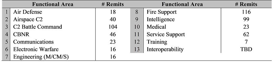
Table 4
IV. IAC’S SQL-SERVER ALGORITHM
Currently, the IAC methodology involves a series of ‘cascading matrices’ to create a fully integrated Operational, System and Technical architecture with dynamic traffic/bandwidth profile and visualization capability (Table 5).
Note: given IAC’s modular construct, additional matrices can easily be added by simply linking one of the new matrices’ variables with a variable already included within the IAC database.
IAC Matrices Linkage

Table 5
Aside from the web based server application, the software prerequisites to run the IAC tool are as follows:
1. Java JRE 1.7
2. MS SQL Server 2008 R2 (or greater)
3. MS Excel 2010 (or greater) - Not required for execution but needed for opening generated files
SQL Server 2008 is used to manage the relationships represented by these matrices. The data represented in each matrix is normalized and stored as tables in a database. An SQL “View” is created for each level of information exchange requirements we wish to generate (Operational, System, and Technical), and the results of each query are stored in separate tables.
The SQL Query used to generate the View expresses the combination of all the matrix relationships required to generate the information exchange requirements. Some performance tweaks still need to be made to the database in order to optimize queries for large datasets.
Currently, transcribing the matrices into the database tables is largely a manual process. As we progress, we will develop a user interface which would allow a subject matter expert to interact with the matrix relationships in an intuitive manner, and store that data directly into the database tables. The challenge lies in representing a series of complex relationships as an intuitive point and click interface.
V. CREATION OF AN IER ‘SUPERSET’ FOR OPERATIONAL NEEDS/REQUIREMENTS ANALYSIS
While integrated, these singular IERs do not constitute the full architectural picture, for with any given series of FS-Unity/Entity, IE, Task and System relationships, there may be a series of combinations by which that specific information can be exchanged along with a series of operational ‘needs’ (requirements) that must be met. Thus, to ensure a fully inclusive integrated architecture, it is imperative that all combinations of relationships be generated.
As a result of significant past research, each of the 570 noted IEs (Paragraph III Table 4) have been assigned Formats and Modes as noted in Table 6.

1x: one-way transmission
Note: VTC would be ‘Vidstream’ going both ways
Table 6
As noted in Table 7, there are four specific forms an information exchange can take: free form, USMTF, VMF and “Undocumented”…exchanges that have yet to be categorized. There is one other aspect of IE Formats that must also be considered and that is ‘Collaborative Planning’—implying a Sender to Receiver back and forth exchange of information. For analysis purposes, IAC models four variations of Collaboration (Table 7).
Table 7
The Properties (Administrative Data) such as Perishability, Criticality, Security Classification, and Precedence allow specific IEs to be ‘assigned’ to specific systems for transmission, such as ‘Trojan Spirit’ for Top Secret transmissions.
There is another degree of increased fidelity that can be gained as a function of the IE format parameters in that ‘one size does not fit all.’ Citing the Commander’s Guidance IE, once again, as an example, a commander may wish to call a subordinate commander by radio, send a text email, draw a graphic and send it as an image, or conduct a VTC. A multitude of options must be captured which allows for multiple formats for each specific IE being generated.
Based on these formats, modes and assigned systems, the IAC algorithm generates all combinations of IERs possible for each associated FS-Unity/Entity in support of all identified tasks that may be executed on the field of battle. Thus, in the end, IAC generates the fully integrated IER Superset associated with the matrixed tables.
As to why we would want to do this, Figure 2 is a case in point.


Figure 2
An Infantry Battalion Commander issues a Fragmentary Order (FRAGO) to one of his Infantry Company Commanders. This FRAGO can be transmitted in four different modes (Voice, Data, Imagery, VidStream), three different formats (‘Free Form,’ USMTF, VMF), over two systems in support of 98 different AUTLs. All told, 2,352 ‘Super Set’ IERs are generated. Ultimately, this IER SuperSet serves as an integral tool to (1) identify operational impacts in the event of operational, system or technical gaps and (2) identify system combinations that can execute information exchanges.
VI. INTEGRATED SV-10C/VIGNETTE DEVELOPMENT
A fully integrated vignette (Mission Thread/User Case) is another byproduct deliverable of the IAC process given IAC’s Superset generation of all possible SV-6 system IERs permutations.
The IERs for such vignettes can be created by a filtering process (Table 8) that selectively sorts information exchanges as a function of:
1. Sender
2. Receiver
3. Message Type (IE)
4. Task/AUTL

Table 8
Once these associated IERs are filtered, an SME can then take and order them in the proper sequence (or verify) to complete the vignette.
VII. ‘REAL TIME’ PRODUCT UPDATES, GAP MITIGATION/ ELIMINATION & ‘WHAT IF?’ ANALYSES
A key strength of the IAC process is the fact that should any of those matrix relationships change as a function of task organization, procurement or, simply, as a function of gap mitigation or ‘what if?’ analyses, all one needs to do is change the relationships within the matrices—or, in the case of added systems, add the new systems to the ‘end’ of the list—and a new, complete set of OV, SV and TV products will be automatically produced, complete with gap analysis output.

Table 9
Table 9 would be one such example where a change in the MTOE exchanges two systems assigned to a Battalion Commander…where one is ‘deleted’ by removing the assigned ‘X’ and another added by placing an ‘X’ in the corresponding cell. Once the updated matrix is imported into IAC a ‘push of a button’ will generate a new set of DoDAF related documents along with a corresponding set of associated ‘gaps’…if any as a function of the change.